
Wicked Beernut Home - Halloween Home
Most of the pictures on this web page are thumbnails. Each thumbnail is ¼ size and ¼ quality of the full image, approximately 3K - 10K bytes. Each thumbnail is a hyperlink to a full image that is approximately 30K - 100K bytes.
 -
-
 -
-
Introduction
My cemetery fence was built from instructions on Screamin' Scott Messinger's Halloween Page. Halloween Net's Iron Fences offers a slightly different version of Scott's instructions.
I constructed 100' of cemetery fence from Scott's instructions. I spaced the 1/2" PVC pipe 6" on center, that's over 600' of 1/2" PVC pipe, 64 angle brackets and over 30 cans of flat black spray paint.
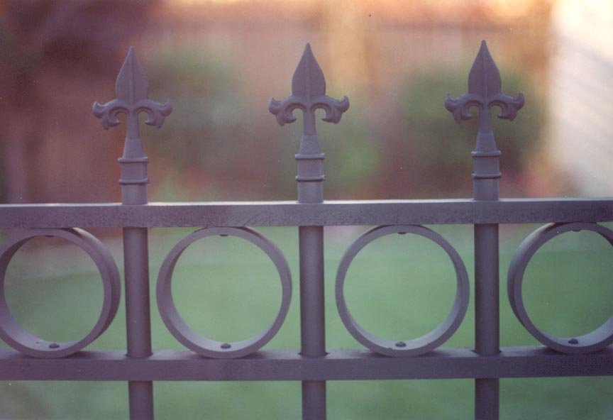
To compliment Scott's design, I added hand-cast plastic finials to each of 183 fence bars. I sandwiched 150 4" PVC rings in between the top 1x2 pine rail and a newly added third 1x2 pine rail. That's almost 300' of 1x2 pine boards, 550 wood screws and 20' of 4" PVC pipe.
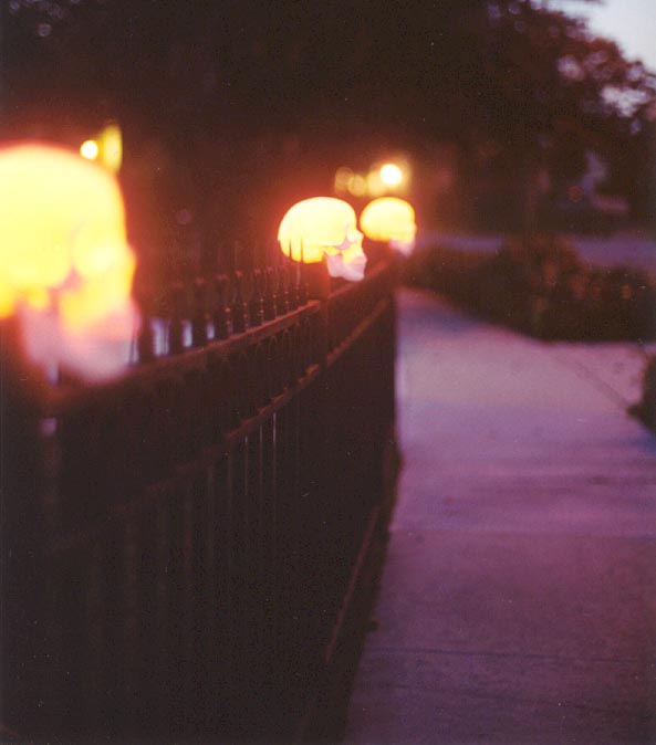
I added life-size, lighted skull finials to each of the 18 fence posts. The lighted skull finials were based on Steve Hickman's Skull Stanchions featured in the Terror Syndicate Home Haunter's Prop Building Handbook #2.
Fence Rings
I cut rings from 4" PVC pipe. The rings were cut approximately 1 1/2" wide to match the width of the 1x2 rails. I drilled a hole in the center of each ring to accept one of the two screws that will secure the ring to the rails. I cut a wire corresponding to half the circumference of the 4" PVC pipe. I used this wire to mark the point at which the second screw hole will be drilled. I drilled the second hole. I cut and drilled 151 4" PVC rings.
Fence Rails
I introduced a third fence rail into Scott's design. I used a 2 3/8" keyhole saw to cut the 1x2 rails to length. This ensures that the rails butt flush to the fence posts. I drilled holes for the fence bars 6" on center using a 7/8" spade drill bit. I drilled holes for the screws that will secure the fence rings 6" on center (centered between the fence bars). The holes for the fence rings are drilled in the bottom of the top rail and in the top of the center rail.
|
Radio Shack Two-Position Dual Row Barrier Strips, 274-656 |
|
Ring Terminals |
|
Intermatic Malibu Low Voltage Cable |
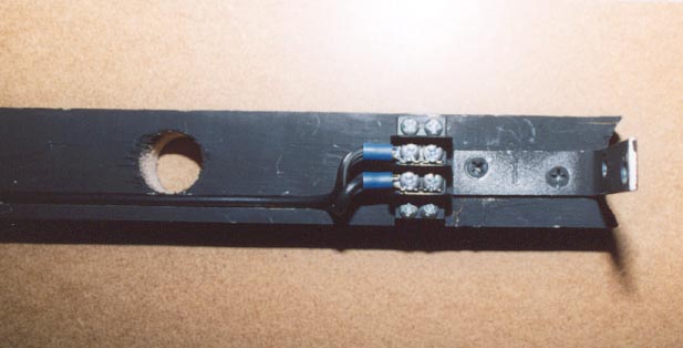
I routed a channel the length of the bottom rail to accept the Intermatic Malibu low voltage cable. The channel is routed on the underside of the bottom rail. I routed the channel as close to the 7/8" fence bar holes as I could. I screwed a Radio Shack two-position dual row barrier strip (274-656) flush with the corner bracket on each end of the bottom rail. I used a hot glue gun to secure the electrical wire in the channel. I soldered ring terminals to either end of the electrical wire and screwed the ring terminals to the barrier strip.
The top fence rail is positioned 3/4" from the top of the fence bars. Make sure that the fence ring screw holes are facing down. Sandwich a ring in between the top rail and the middle rail and secure the ring to the rails using a pair of #10 3/4" round head screws.
Once all of the rails are secured to the bars and all of the rings are secured to the rails, I positioned each section of fence on end and applied epoxy at the point where each ring meets the rail (top and bottom). The epoxy is applied almost like a "weld". Once the epoxy was dry, I turned each section of fence over and applied epoxy to the other side of each ring. The epoxy ensures that the rings won't turn.
Fence Posts
Scott suggests that you can either,
I opted for the latter technique, but I found that it was very difficult to back out the short screws far enough to allow the rebar to pass while still securing the 1/2" PVC pipe to the inside wall of the 2" PVC pipe fence post.
Instead, I created a "spindle" using a 2" to 1/2" PVC reducer bushing and a 1 1/2" to 1/2" PVC reducer bushing at either end of the 1/2" PVC pipe which was originally secured to the inside wall of the 2" PVC pipe fence post. The spindle centers the 1/2" PVC pipe within the 2" PVC pipe fence post.
|
2" Slip x Slip PVC Coupling |
$0.75 |
|
2" to 1/2" PVC reducer bushing |
$1.19 |
|
1 1/2" to 1/2" PVC reducer bushing |
$0.72 |
|
Total (per fence post) |
$2.66 |
The fence post is next wired to connect the adjacent rails and the skull finial.
|
Radio Shack Two-Conductor Female Molded Nylon Connector, 274-222 |
|
Ring Terminals |
|
Wire Nuts |
|
Intermatic Malibu Low Voltage Cable |
Cut one 8" length of electrical wire corresponding to each adjacent rail. An inner fence post will have two adjacent rails and will require two 8" lengths of electrical wire. An outer fence post will have one adjacent rail and will require one 8" length of electrical wire. Cut one piece of electrical wire the same length as the fence post (approximately 40"). Strip the ends of the electrical wire. Connect a pair of ring terminals to one end of the 8" length of electrical wire. Connect a Radio Shack female molded nylon connector to one end of the 40" length of electrical wire. The ring terminals and connectors can be crimped on the wire. I prefer to use solder.
I drilled a hole through the fence post right where the angle bracket secures the bottom rail to the post. Actually, I drilled a pair of immediately adjacent holes in order to allow the electrical wire to pass.
I drilled a hole through the 1 1/2" to 1/2" reducer bushing in order to allow the 40" length of electrical wire to pass. The 40" length of electrical wire is fed through the hole with the nylon connector on the top of the spindle.
Insert the spindle into the fence post ensuring the stripped ends of the 40" length of electrical wire are accessible. Feed the 8" length(s) of electrical wire through the hole(s) in the side of the fence post. Attach one lead from each of the electrical wires using a wire nut. Completely insert the spindle into the fence post. Use a coat hanger to fish out the nylon connector from the top of the fence post if necessary.
A screw can be inserted through the fence post and either of the two bushings into the rebar in order to hold the rebar in place although I didn't find this necessary.
Fence Bar Finials
|
Iron Finial (Model) |
|
2" length of 5/8" Wood Dowel |
|
Klean Klay |
|
Foamcore |
|
Two 3" lengths of Heavy-Gauge Electrical Wire |
|
Silicone |
|
Silicone Release Agent (Liquid) |
|
Synair Synlube 1711 Release Agent (Spray) |
|
Por-A-Kast |
|
Exact-o Knife |
|
Straight-Edge (Framing Square) |
|
3 ounce Dixie bathroom cups (one per finial) |
|
Scale |
|
Wooden Popsicle Sticks |
|
Three 6" Wood Clamps |
|
Hardboard (Two pieces approximately 4" x 6") |
|
Sandpaper |
|
Scissors |
|
Wire Cutters |
|
Epoxy |
|
Clear Acrylic Spray |
|
Black Spray Paint |
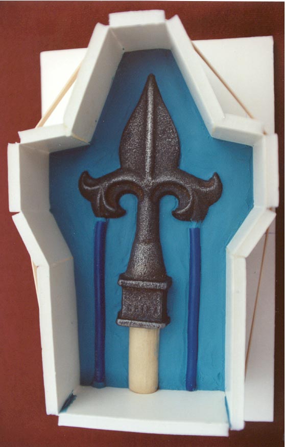
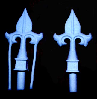
A wood dowel is placed in the end of the finial. Once cast, this is the portion of the finial that will be inserted into the fence bar. I started with a 5/8" wood dowel and sanded it down until it would slip into a 1/2" PVC pipe. I sprayed the sanded dowel with two coats of clear acrylic to keep the wood from sticking to the silicone that will be used to make the mold.
I placed the wood dowel into the base of the finial. This is a "round peg" in a "square hole". I filled the corners of the finial base around the dowel with Klean Klay.
I centered the finial on a 5" x 8" piece of foam core and traced the outline of the finial. I then drew lines that would correspond to the form approximately 1/2" from the finial. Your form should be approximately 2" high. My form was approximately 15 1/2" long. Start with a slightly longer length of foamcore, say 18".
Begin at the base of the finial. Mark the width of the base on the form core. Using an Exact-o knife, cut halfway through the foamcore. This will allow you to snap and bend the foam core at the desired angle. Proceed in this way to make each side of the form. My form had eleven sides. Once you have formed the final side, you can cut the form to the desired length.
My finial was 7/8" thick at its thickest point (the base). You will want to start with a block of Klean Klay that is at least 3/4" thick and slightly wider than the form. Press the finial into the clay up to the centerline. Press two lengths of heavy-gauge electrical wire into the clay extending from the lowest point of the finial.
I used the blade of a kitchen knife to work the clay around the edges of the finial such that it was flush and level with the centerline of the finial and the electrical wire. I used a small amount of clay to "transition" the electrical wire into the finial. The electrical wire should appear as an extension of the finial. There shouldn't be any gaps between the electrical wire and the finial.
I centered the form over the block of clay and gently pressed the edges of the form into the clay. I used a knife to cut out a pattern corresponding to the inside edge of the form. I then wrapped the form around the clay. I used Scotch tape to hold the mold closed. I ran a bead of Klean Klay along the inside corner where the form came together. I again used a knife to ensure the clay was flush with the sides of the form.
Place a sheet of plastic wrap over the form. Gently press the plastic wrap into the form and onto the clay and finial. Pour water onto the plastic wrap from a measuring cup. The water should be at least 1/4" above the highest point of the finial. Note the amount of water that you've poured from the measuring cup. This will serve as an approximation as to how much silicone you will need.
Mix the silicone as recommended. Pour the silicone over the finial and allow to the silicone to completely dry. Once the silicone is dry you can remove the sides of the form. Remove the clay from the mold, the finial and the electrical wire. Try not to disturb the finial and the electrical wire. If the finial and/or electrical wire are disturbed they can simply be put back in place.
Clean the mold with alcohol. Replace the form. Again, secure the form with tape and seal the corner with clay. Apply release agent to the silicone. I applied a liquid release agent using a small brush so as not to get release agent on the finial.
Mix an equivalent amount of silicone. Pour the silicone into the mold. Allow the mold to dry. Remove the form and separate the two halves of the mold. You may need to remove excess silicone from the holes corresponding to the wood dowel and the electrical wires.
I used Por-A-Kast to cast the finials. The Por-A-Kast prepolymer and curative are supposed to be mixed one to one by volume. Given the small volume involved, I opted to mix them one to one by weight.
The two halves of the two-part mold will need to be secured together. I chose to use wood clamps. I sandwiched the mold between two pieces of 1/2" hardboard. The hardboard helps to evenly distribute the pressure of the clamps.
I clamped the two halves of the two-part mold together using three 6" wood clamps and filled the mold with water from a measuring cup. I used the water to estimate the total volume of casting material that would be required per finial. Note that the clamped mold should hold water. If it won't hold water, it won't hold the prepolymer and curative. If the mold leaks, try tightening the clamps.
I poured the water from the mold, removed the clamps, separated the two halves of the mold, blotted it with a paper towel and allowed it to completely dry.
I sprayed the mold with Synair Synlube 1711 release agent before pouring each cast. Technically, a release agent isn't required with a silicone mold, but since I intended to cast almost 200 finials, I wanted to minimize the wear and tear on the mold.
I reassembled the mold using the hardboard and wood clamps.
I placed a three-ounce Dixie bathroom cup on a small digital scale. I poured an amount of prepolymer into the Dixie cup equivalent to half the total volume approximated using the water. I noted the weight of the prepolymer in grams and poured an equivalent amount of curative into the Dixie cup.
I ended up using 17 grams of prepolymer and 17 grams of curative. Of course, this is somewhat specific to my mold and the finial from which it was made, but it gives you a sense as to how much casting material is required to make a finial.
I stirred the prepolymer and curative in the Dixie cup with a wooden Popsicle stick until they were mixed thoroughly. If the Popsicle stick is wiped cleaned with a paper towel, it can be reused. You should use a clean Dixie cup for each finial. As the prepolymer and curative are mixed, you will be able to feel heat through the sides of the Dixie cup. I pinched the lip of the Dixie cup to form a small spout and poured the casting material into the mold through the large hole. The casting material should be level with the top of the mold. The casting material should be visible in each air vent.
From the casting material left in the Dixie cup, you will be able to see that it hardens in a matter of minutes. I allowed the cast to dry for 15 minutes before attempting to remove it from the mold. You should be able to easily separate the two halves of the mold and remove the resulting finial. The air vents can be cut off using a pair of scissors or wire cutters. Cut each air vent with the curvature of the finial and use light sandpaper to finish off the edges.
Just 182 more and I'll be done. At approximately 20 minutes per finial, I'll be at this for a while.
You may need to sand the post of the finial in order for it to fit into the 1/2" PVC fence bar. I used epoxy glue to secure each finial to the fence bar. I chose to spray paint each finial black.
Fence Post Finials
The fence post finials are lit using,
|
Intermatic Malibu Low Voltage Landscape Lights LX19414T |
The LX19414T package includes,
and sells for about $30. Each fence post finial requires,
|
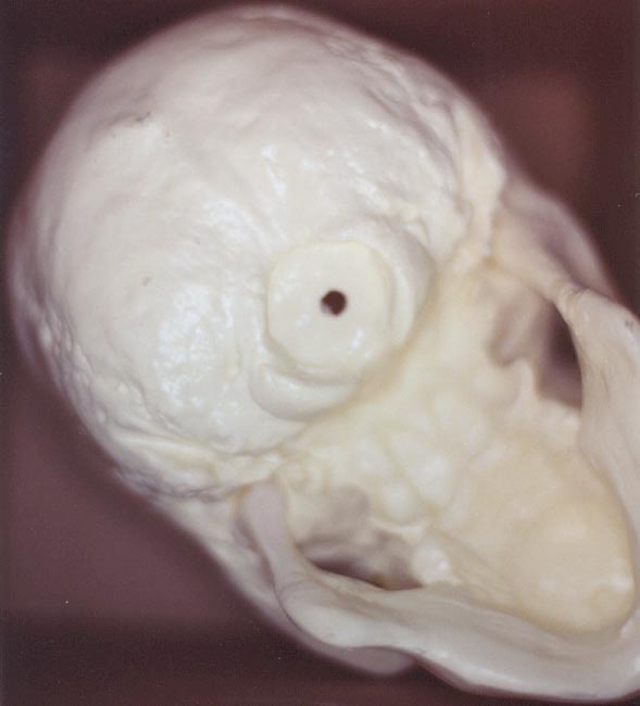
Bucky Skull (No Calvarium Cut), Boneyard Bargains, CH-S2 |
|
2" Slip x Slip PVC Coupling |
|
2" to 11/2" PVC Reducer Bushing |
|
4 3/8" x 1 1/2" PVC Pipe |
|
Radio Shack Two-Conductor Male Molded Nylon Connector, 274-222 |
|
Small Screw |
Note that this is the newer Bucky skull, CH-S2, not the original Bucky skull, CS-20/4. The newer Bucky skull emits a warm glow when illuminated using a four watt landscape bulb. The original Bucky skull won't pass light!!!
Other materials and equipment,
|
2" Keyhole Saw and Drill |
|
Flat Black Spray Paint |
|
PVC Cement |
|
Five Minute Epoxy |
|
White Epoxy Paste (optional) |
|
Dremel with Grinding Drum |
The skull finial will be illuminated using a tier light (LX1). The parts of the tier light that will be used are the socket, the wire leads and the riser. The other parts (including the lens, top tier, bottom tier and ground stake) can be discarded.
I opted to replace the cable connectors on the wire leads with a Radio Shack two-conductor male molded nylon connector. The female molded nylon connector that comes as part of the pair (274-222) was attached to the electrical wire in the fence post.
I opted to remove the jaw springs from the Bucky skull. With the springs still attached, I applied five-minute epoxy at the points where the jaw comes in contact with the skull. Allow the epoxy to dry for five minutes. You can then remove the screws and the nuts and bolts that hold the springs in place. I opted to fill the screw holes with a dab of white epoxy paste.
 -
-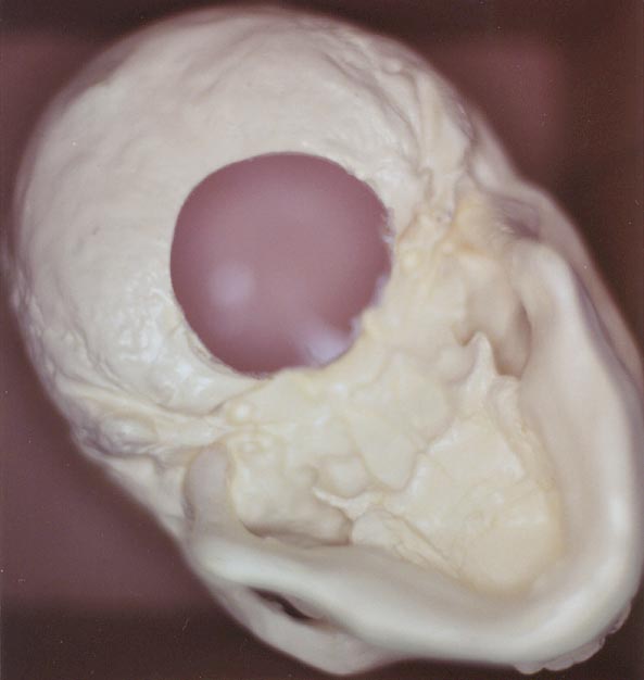
Use the 2" keyhole saw and drill to cut a 2" hole in the base of the Bucky Skull.
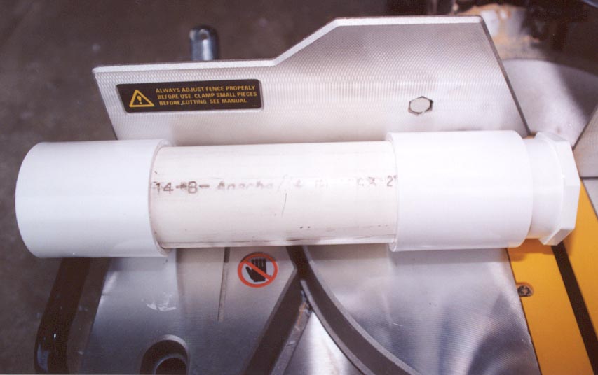
Using the Dremel, grind down the lip on the inside of the 2" to 1 1/2" PVC reducer bushing such that the 4 3/8" x 1 1/2" PVC pipe can slide freely. Remove the PVC pipe from the bushing.
Insert the 2" to 1 1/2" PVC reducer bushing into the 2" slip x slip PVC coupling. Use a saw to cut the bushing flush with the top of the coupling. I used a compound miter saw to cut the bushing. Reinsert the 4 3/8" x 1 1/2" PVC pipe such that 1" of PVC pipe protrudes from the top of the coupling. There should be approximately 1/2" of 1 1/2" PVC pipe protruding from the bottom of the coupling. Insert the 1" length of 1 1/2" PVC pipe into the base of the skull. The 1" length of pipe should just enter the base of the skull.
Remove the assembly from the base of the skull. Carefully mark the relative position of the 1 1/2" PVC pipe with respect to the coupling. Disassemble the 1 1/2" PVC pipe, 2" to 11/2" PVC reducer bushing and 2" slip x slip PVC Coupling.
Apply PVC cement to the inside of the coupling. Quickly insert the reducer bushing into the coupling. Be prepared to use a rubber mallet, if necessary, to completely insert the reducer bushing such that it is again flush with the coupling.
Apply PVC cement to the inside of the reducer bushing. Quickly insert the 1 1/2" PVC pipe into the reducer bushing from the bottom. Be prepared to use a rubber mallet, if necessary, to completely insert the 1 1/2" PVC pipe into the reducer bushing such that it is aligned with the mark. Wipe any excess PVC cement from the length of 1 1/2" PVC pipe that extends from the top of the coupling.
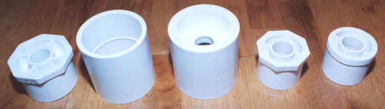
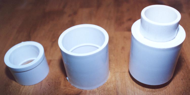
The following picture illustrates (from left to right), the 2" to 1 1/2" PVC reducer bushing, the 2" slip x slip PVC coupling and the finished PVC assembly.
Spray paint the PVC assembly with flat black spray paint.
Generously apply five-minute epoxy in and around the 2" hole in the base of the skull. Insert the PVC assembly into the hole and allow the epoxy to dry.
The tier light socket and riser assembly will slide into the bottom of the 1 1/2" PVC pipe. Align the bottom of the fixture with the bottom of the 1 1/2" PVC Pipe. Drill a small hole through the 1 1/2" PVC pipe into the fixture. Secure the fixture to the pipe using a small screw. The head of the screw must be small enough in order to allow the completed assembly to slip on the fence post.
Don't epoxy or cement the fixture to the 1 1/2" PVC pipe. You will want to be able to remove the fixture in order to replace the bulb. The completed skull finial should slip on and off the fence post. Don't epoxy or cement the coupling to the fence post. You will want to be able to remove the skull finial for storage. I take the skull finials in every night.
Plug the male molded nylon connector of the skull finial into the female molded nylon connector attached to the electrical wire in the fence post and you are ready to go.